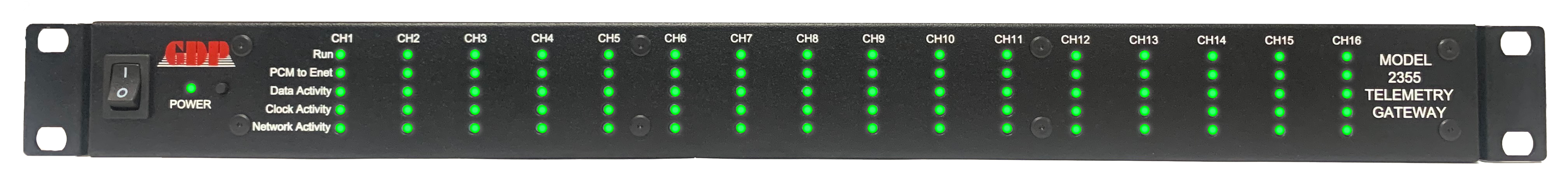
Model 2355 Telemetry Gateway
The Next Generation Model 2355 Telemetry Gateway is the latest in Telemetry-over-IP transport. The unit supports PCM-to-Ethernet packetization and Ethernet-to-PCM depacketization and is controlled utilizing our new web-based Browser GUI. The MD2355 is a 1U rack mount gateway available in 16, 12, 8 & 4 channel configurations that facilitate the transfer of data, which can originate from a variety of sources over an Ethernet network. The basic input is a synchronous serial digital data stream and its coherent clock. This serial data source is packetized, placed in an Ethernet wrapper, and output to a network environment.
A second model, MD2355 or our legacy MD2350-(M02, M04, M12) gateways, can be connected to the network to receive and extract the original data from the Ethernet packets. This reconstructed data stream is output with a coherent clock at the same data rate as the original source. Each channel can be independently configured as PCM-to-Ethernet packets or Ethernet-to-PCM (Serial Data & Clock) depending on your application. The unit supports a variety of Ethernet formats, including IREG 218-2010 & 2020, GDP Formats, Optional Chapter 10/11 format, and others. Packet tagging and time transport via NTP and PTP come standard. IRIG B is optional. This compact high-density transport solution will bring down the per/channel costs while increasing the system mean time between failures (MTBF).

UP to 16 channels at Sustained Bit Rates from 100 bps to greater than 50Mbps
Available in 16, 12, 8, 4 Channel Configurations
Low Latency & Low Channel-to-Channel Skew
New Easy-to-use Web Browser GUI with Enhanced Channel Status and Error Reporting
Frame Sync/Pattern Detector for each CH Supporting Frame Aligned and Non–Frame Aligned Modes
Link Test PRN BERT Function; PRN Pattern Generation/Simulation (PRN 11, 15 & 23)
Time Input / Output / Packet Tagging
- NTP & PTP IEEE-1588 (Standard)
- IRIG B STD 200 *
Additional Features
- Ethernet 10 / 100 / 1000 base-T; UDP Data Protocol; Unicast or Multicast; Ethernet Auto detect; Auto rate detection/ tracking;
- Supports IRIG 218-10 & 20 and Optional IRIG 106 Ch 10/11 * & AE Format*
- Independent Ethernet Control & Data with SFP interfaces 1 Gbps-over-Copper SFP or Fiber SFP (Copper SFPs Included)
- TTL/RS-422 Digital Data & Clock I/O
- All TTL Digital I/O Standard
- RS-422 I/O *(Optional) in Increments of 2 Channels (Specified with order)
- Bit sync inputs *(Optional)
- Redundant Power Supply *(Optional
- Backward-compatible with 2350
- Output error insertions
- TRMS Software Compatible
PCM Digital I/O: PCM Data I/O can be ordered from the factory as TTL Data & Clock or RS-422 Data & Clock in groups of 2, with each one of the 16 channels assigned as input or output by the GUI software. The standard configuration from the factory is all TTL.
Frame Synchronizer/Pattern Detector: An internal frame synchronizer is provided for each channel supporting pattern sync to the incoming PCM stream. In addition to pattern sync status, the Frame Sync can align the start of each minor frame to the start of a network packet. This feature supports simplified software decommutation directly from the Ethernet.
Small Form Pluggable (SFP) Interface Option: Independent Control and data ports are supported via SFPs. Copper SFPs are provided standard. Fiber SFPs are also supported.
New Browser GUI

CHANNEL OVERVIEW
When power is first applied to the MD2355, the indicators for Channels 1 through 16 blink Red until the link is established. When the user places the channels in RUN mode, the “RUN” indicator displays a check mark inside a green circle. Placing a channel in the Halt mode causes the appropriate “RUN” channel indicator to be show an “x” encircled in red. Each one of the fields (Run, Data Act, Net. Act, Frame Sync) will act according to its status.

GENERAL SETUP
The MD2355 has two independent ports, one Management and one Data, for security & Network flooding protection. In addition to the Web Browser GUI, the MD2355 may be controlled through the GDP TRMS application to address the ‘System Level’
configurations that comprise a data acquisition/processing system.


CHANNEL SETUP
By selecting any one of the sixteen Channel settings, each channel in the unit may be set to accommodate a specific signaling requirement, Serial-to-Ethernet or Ethernet-to-Serial.
Ordering Options
Base
| MD2355- w/M16 Bundle | Sixteen Channel Telemetry Gateway Bundle Including: Pick Eight Total I/O Channel Cards if Different than Standard Config. QTY (8): Dual TTL I/O Channel Card(s) [Std Config. qty 8 – 2TTL Cards] QTY (0): Dual RS422 I/O Channel Card [Std Config. qty 0 -2RS422 Cards] IRIG 218-10, IRIG 218-20 & GDP Formats NTP/ PTP Time; Frame Sync Pattern Detector |
| MD2355-w/M04 Bundle | Four Channel Telemetry Gateway Bundle Including: PickTwo Total I/O Channel Cards if Different than Standard Config. QTY (2): Dual TTL I/O Channel Card(s) [Std Config. qty 2 – 2TTL Cards] QTY (0): Dual RS422 I/O Channel Card [Std Config. qty 0 -2RS422 Cards] IRIG 218-10, IRIG 218-20 & GDP Formats NTP/ PTP Time; Frame Sync Pattern Detector |
| MD2355-w/M12 Bundle | Twelve Channel Telemetry Gateway Bundle Including: Pick Six Total I/O Channel Cards if Different than Standard Config. QTY (6): Dual TTL I/O Channel Card(s) [Std Config. qty 6 – 2TTL Cards] QTY (0): Dual RS422 I/O Channel Card [Std Config. qty 0 – 2RS422 Cards] IRIG 218-10, IRIG 218-20 & GDP Formats NTP/ PTP Time; Frame Sync Pattern Detector |
| MD2355-w/M08 Bundle | Eight Channel Telemetry Gateway Bundle Including: Pick Four Total I/O Channel Cards if Different than Standard Config. QTY (4): Dual TTL I/O Channel Card(s) [Std Config. qty 4 – 2TTL Cards] QTY (0): Dual RS422 I/O Channel Card [Std Config. qty 0 – 2RS422 Cards] IRIG 218-10, IRIG 218-20 & GDP Formats NTP/ PTP Time; Frame Sync Pattern Detector |
Options
| OP2355-2TTL |
Dual TTL I/O Channel Card
|
|
OP2355-2RS422
|
Dual RS422 I/O Channel Card
|
|
OP2355-2BS.TTL
|
Dual Bit Sync Card Option – TTL Input
|
|
OP2355-2BS.RS422
|
Dual Bit Sync Card Option – RS422 Input
|
|
OP2355-CH10
|
Chapter 10 Ethernet (In/Out)
|
|
OP2355-IRIG-B
|
IRIG Time Input/Output Card
|
|
OP2355-PS2
|
Redundant Power
|
Send us your telemetry requirements!
Unlock precise data insights with our tailored telemetry solutions – send us your telemetry requirements today and elevate your business intelligence